
NHTSA ID Number: 10165799
Manufacturer Communication Number: Remotestart
Summary
extended range installation instructions.
5 Affected Products
Vehicles
VOLKSWAGEN | ARTEON | 2020 |
| VOLKSWAGEN | ATLAS | 2020 |
| VOLKSWAGEN | JETTA | 2019-2020 |
| VOLKSWAGEN | TIGUAN | 2020 |
Installation instructions
Instructions de montage
Key fob for remote engine start
Télécommande radio pour démarrage à distance
000.065.760
Preparation
Carry out all work according to current workshop literature:
– Disconnect battery → ELSA, RG 27.
– Remove cover on end of dash panel on driver side → ELSA, RG 70.
– Remove middle trim panel on A-pillar on driver side → ELSA, RG 70.
– Remove upper trim panel on A-pillar on driver side → ELSA, RG 70.
– Remove lower trim panel on A-pillar on driver side → ELSA, RG 70.
– Remove cover in footwell → ELSA, RG 68
– Remove storage compartment on driver side → ELSA, RG 68
– Remove sun visor on driver side → ELSA, RG 68
Installing receiver and connecting wiring harness
1. Secure receiver -1- to side of dash panel using suitable workshop, as shown.
1. 1. Secure eye-terminal of brown wire to earth (ground) point -1-.
1. Push the fuse holder with the red wire into fuse number 20.
Is there a Fuse in Place use place number 7 or 8. In case there is also a fuse lower or greater than 10amp in place pull this fuse out and push it in to the fuse holder on the harness instead off the 10amp fuse.
1. Release connector -1 and pull it off onboard supply control unit (also known as Body Control Module in USA) (BCM -J519-).
2. Release connector housing and slide open upper part.
3. Insert yellow wire of wiring harness into chamber C54 of connector.
Note
If chamber C54 is already in use, unpin wire and insert it into connector housing supplied and connect to connector. Then insert yellow wire of wiring harness into chamber C54.
4. Insert connector into onboard supply control unit (also known as Body Control Module in USA) (BCM -J519-) and lock.
Installing and connecting window aerial
Note
The temperature required when bonding the window must lie between 18 – 40°C (64 – 104°F). The glass in the area of the bonding point must be dry and free of dust and grease.
1. Thoroughly clean bonding point -a- on right, next to mirror base with the cleaning cloth supplied.
WARNING
The driver’s field of view must, under no circumstances be restricted.
2. Bond aerial -1- on right next to mirror base, as shown.
1. Release the headlining slightly in the area of the windscreen to allow the wiring to be routed better.
2. Route aerial wire, under headlining, from aerial -2- to A-pillar.
WARNING
Observe safety precautions for pyrotechnical components, refer to current instructions in Volkswagen Workshop Equipment literature. Route wiring behind curtain airbag and secure it appropriately. Do not trap or damage the curtain airbag when installing the pillar upper trim. The function of the curtain airbag must be guaranteed under all circumstances.
3. Continue to route aerial downwards along A-pillar to receiver -1- (arrows).
Reinstall all trim panels and components according to Volkswagen Workshop literature, this is basically carried out in the reverse order of removal.
Note
- After connecting the battery, ensure that the vehicle accessories (radio, clock, electrical windows) are checked in accordance with the workshop manual.
- After fitting is completed, the ESP light may light up. In this case, basic setting of the steering angle sensor -G85- must be carried out.
Coding the remote start feature
– Connect the battery → ELSA; repair group 27.
– Connect a vehicle diagnostics, measurement and information system -VAS 505X- to the vehicle → Electrical system, repair group 97; wiring, vehicle diagnostics, measurement and information systems; connecting a vehicle diagnostics, measurement and information system -505X-. – Select the operating mode “Guided Troubleshooting” and then the respective vehicle within the vehicle diagnostics, measurement and information system -VAS 505X-.
– After querying the control units, select the “Functions/component selection” via the button “Jump” and then sequentially the following menu options:
-
- Software version management
- Adapting Software
- Select option 2 (SW update via measure code)
– Enter the 4 character AM code “425D”. The online connection is created after code entry and the software update carried out. If the program aks for a check number, please enter “7”.
– Quit the “Guided Troubleshooting” using “Go to”. All error memory entries are deleted.
Adapting remote control
– Switch on ignition.
– Select operating mode “Start diagnostics” (Basic settings) on vehicle diagnostic tester and identify the
vehicle.
– Select operating mode “Control unit self-diagnosis” for diagnostic address 09 (BCM -J519-).
– Select menu item “Adapting RF Transmitter via barcode”.
– Start process.
Préparatifs
Faire tous les travaux suivant la documentation de Volkswagen :
– Débrancher la batterie → ELSA, RG 27.
– Démonter le cache sur le côté du tableau de bord, côté conducteur → ELSA, RG 70.
– Démonter le revêtement des montants A, au centre côté conducteur → ELSA, RG 70.
– Démonter le revêtement des montants A , en haut côté conducteur → ELSA, RG 70.
– Démonter le revêtement des montants A , en bas côté conducteur → ELSA, RG 70.
– Démonter le cache du plancher côté conducteur → ELSA, RG 68
– Démonter le vide-poches côté conducteur → ELSA, RG 68
– Démonter le pare-soleil côté conducteur → ELSA, RG 68
Monter le récepteur et raccorder le faisceau de câbles
1. Fixer le récepteur -1- de la manière indiquée, sur le côté du tableau de bord, avec des moyens adaptés à l’atelier.
1. Visser le câble marron avec une vis à oeillet sur le point de la masse -1-.
1. Pousser le porte-fusible avec le fi l rouge dans le fusible numéro 20.
1. Déverrouiller et retirer le connecteur -1- du calculateur du réseau de bord (BCM -J519-).
2. Déverrouiller le boîtier du connecteur et ouvrir la partie supérieure.
3. Mettre le câble jaune du faisceau de câbles dans le logement C54 du connecteur.
Indication
Si le logement C54 est occupé, enlever le câble, le mettre dans le boîtier fourni, et le raccorder au connecteur. Ensuite, mettre le câble jaune du faisceau de câbles dans le logement C54.
4. Insérer et verrouiller le connecteur sur le calculateur du réseau de bord (BCM -J519-).
Monter et raccorder l’antenne du pare-brise
Indication
La température pour coller l’antenne du pare-brise doit être de 18 à 40°C (64 – 104°F). Dans la zone de fixation, la vitre doit être sèche, sans poussière et sans graisse.
1. Nettoyer soigneusement la zone de fi xation -a- à droite à côté du support du rétroviseur, avec le chiffon fourni.
ATTENTION
Il ne faut en aucun cas gêner le champ de vision du conducteur.
2. Coller l’antenne -1- de la manière indiquée , à droite à côté du support du rétroviseur.
1. Détendre légèrement le pavillon dans la zone du parebrise, afi n de mieux faire passer le câble de l’antenne.
2. Poser le câble de l’antenne -2- jusqu’au montant A sous le pavillon.
ATTENTION
Tenir compte des consignes de sécurité pour les composants pyrotechniques, suivant la documentation de Volkswagen. Poser le câble derrière l’airbag de tête, et le fi xer d’une manière adaptée. Lors du montage de l’habillage supérieur du montant, ne pas coincer l’airbag de tête. Il faut assurer le fonctionnement de l’airbag de tête dans toutes les circonstances.
3. Poser le câble de l’antenne sur le montant A vers le bas, vers le récepteur -1- (fl èche), et le raccorder.
Remonter tous les habillages et les composants suivant la documentation de Volkswagen, le montage se fait de la même manière dans le sens inverse du démontage.
Indication
• Après avoir branché la batterie, contrôler les accessoires du véhicule (radio, pendule, lève-vitres électriques) avec le manuel d’atelier.
• Après le montage, il se peut que le voyant ESP soit allumé. Dans ce cas, il faut faire le réglage de base du capteur de l’angle de braquage -85-.
Codage de la fonction de démarrage à distance
– Brancher la batterie → ELSA, RG 27.
– Raccorder le système de diagnostic, de mesure et d’information VAS 505X au véhicule → Système électrique, RG 97, câblage, diagnostic du véhicule. systèmes de mesure et d’information, Raccordement du système de diagnostic, de mesure et d’information -505X-.
– Sélectionner le mode « Localisation guidée des défauts », et affi cher ensuite dans le système de diagnostic, de mesure et d’information VAS 505X, le véhicule correspondant.
– Après avoir consulté le calculateur, sélectionner l’option « Functions/component selection » (avec le bouton « Jump »), et ensuite, sélectionner l’une après l’autre, les options suivantes :
-
- Gestion de la version du logiciel
- Adapter le logiciel
- Sélectionner l’option 2 (mise à jour du logiciel avec le code)
– Taper le code AM à 4 caractères « 425D ». Après avoir tapé le code, la connexion en ligne va être établie, et le logiciel est mis à jour. Si le programme réclame un chiffre de contrôle, taper « 7 ».
– Quitter la localisation guidée des défauts avec « Go to ». Tous les défauts enregistrés dans la mémoire vont être effacés.
« Apprentissage » de la télécommande
– Mettre le contact.
– Sélectionner le mode « Démarrer le diagnostic » (Base setting) sur le contrôleur de diagnostic du véhicule, et identifi er le véhicule.
– Sélectionner le mode « Autodiagnostic calculateur » pour l’adresse de diagnostic 09 (BCM- J519-).
– Sélectionner l’option « Adapting RF Transmitter via barcode ».
– Démarrer la procédure.
SEOCONTENT-START
General information
concerning these installation
instructions
Dear Customer,
Thank you for choosing this Genuine
Volkswagen of America Accessories
product.
Please carefully follow the steps
described in this booklet and heed
all warnings as well as safety
information. Damage caused through
non-observance is excluded from
any liability.
VWoA Performance & Accessories
is continually working on the further
development of all products. Please
understand that we must therefore
reserve the right to alter any part
of the vehicle and its equipment
or technical specifi cations at any
time. The details concerning scope
of delivery, design and function of
the product refer to the information
available at the time of publication.
No legal commitment is therefore
implied by the details, illustrations
and descriptions in this booklet.
We recommend that the installation
be carried out by a dealership or a
qualifi ed workshop.
WARNING
Texts with this symbol contain
information on safety. They help
protect you from accidents and
injury.
Note
Texts with this symbol indicate how
you can prevent damage to your
vehicle.
Texts with this symbol contain
additional information.
F
Informations générales
relatives à cette notice de
montage
Cher client,
Nous sommes heureux que vous
ayez choisi un produit de Genuine
Volkswagen of America Accessories.
Les opérations indiquées dans
ces instructions de montage et
consignes de sécurité doivent être
impérativement respectées. Nous
déclinons toute responsabilité pour
des dommages résultant de leur
non-respect.
VWoA Performance & Accessories
oeuvre en permanence au
perfectionnement de tous ses
produits. Nous vous remercions
de votre compréhension, des
modifi cations du matériel fourni
étant en effet possibles à tout
moment, que ce soit sur le plan
de la forme, de l’équipement ou
de la technique. Les indications
concernant l’étendue de livraison,
l’aspect et les fonctions des produits
sont conformes aux informations
disponibles au moment de la clôture
de la rédaction. Les indications,
illustrations et descriptions fi gurant
dans la présente notice ne revêtent
aucun caractère contractuel.
Nous recommandons de laisser
faire le montage par un partenaire
Volkswagen ou par un atelier
spécialisé.
ATTENTION
Les textes suivis de ce symbole
contiennent des informations
concernant votre sécurité et
vous informent des risques
d’accidents et blessures
éventuels.
Remarque
Les textes accompagnés de ce
symbole vous informent comment
éviter des dommages éventuels sur
votre véhicule.
Les textes suivis de ce symbole
comportent des informations
supplémentaires.
– 3 – Distributed and printed by Volkswagen of America Performance & Accessories
EN
WARNING
Improper installation procedures can cause serious personal injury.
• Installation should be performed only by a qualifi ed technician.
• Read all instructions thoroughly before starting.
• Observe all safety precautions when working under a vehicle.
• Beware of sharp edges to help prevent cuts.
• Always wear safety glasses to help protect eyes.
• Always wear protective gear such as gloves and use caution when using hand tools.
WARNING
Using unsuitable or damaged sockets and connecting cables and disregarding accepted safety practices
may cause short circuits, accidents, and serious or fatal personal injury.
• Never use damaged sockets and connecting cables. Check connectors and cables for damage before
use.
• Never allow connectors to come into contact with moisture, water and other fl uids.
• The remote start feature can only be retrofitted on vehicles with an automatic transmission.
• The installation of the original retrofitting remote start feature must be carried out by a competent workshop.
Special tools and the accompanying literature specific to the car are required for proper installation and function.
Incorrect installation may damage the vehicle.
• Secure the wires so that they cannot come into contact with any rotating or other moving parts and so that they
cannot chafe against any sharp metal or plastic edges.
• All rights to make technical changes without notice are reserved.
Safety notes
FR
ATTENTION
Les opérations de montage non conformes peuvent entraîner des blessures graves.
• Le montage ne doit être réalisé que par un technicien qualifi é.
• Avant le montage, il faut étudier soigneusement toutes les instructions.
• Il faut respecter toutes les consignes de sécurité concernant les opérations sous le véhicule.
• Faire attention aux arêtes coupantes, afi n d’éviter des blessures.
• Il faut toujours mettre des lunettes de protection.
• Il faut toujours mettre des vêtements de protection (gants etc.), et être prudent lors de l’utilisation des
outils.
ATTENTION
L’utilisation de douilles et de câbles inadaptés ou endommagés, ainsi que le non-respect des mesures
de sécurité courantes, peuvent provoquer des courts-circuits, et des accidents, ainsi que des blessures
graves et même mortelles.
• Ne jamais utiliser de douilles ou de câbles endommagés. Avant d’utiliser des connecteurs ou des câbles,
contrôler s’ils ne sont pas endommagés.
• Ne jamais mettre les connecteurs en contact avec de l’humidité, de l’eau ou d’autres liquides.
• La fonction de démarrage à distance ne peut être installée ultérieurement que sur les véhicules avec une boîte
de vitesses automatique.
• Le montage de la fonction de démarrage à distance d’origine en rétrofit doit se faire dans un atelier spécialisé et
qualifié. Pour le montage adapté et le fonctionnement conforme, il faut des outils spéciaux et la documentation
du véhicule concerné. Un montage non conforme peut éventuellement endommager le véhicule.
• Fixer les câbles de manière à ce qu’ils ne soient pas en contact avec des éléments mobiles, et qu’ils ne puissent
pas frotter contre des éléments métalliques ou en plastique, avec des arêtes coupantes.
• Sous réserve des droits de réalisation de modifications techniques sans préavis.
Consignes de sécurité
– 4 – Distributed and printed by Volkswagen of America Performance & Accessories
Item Designation Qty.
1 Receiver 1
2 Key fob 1
3 Aerial 1
4 Harness 1
5 Label with Key Data 1
6 Cleaner 1
7 Connector Housing 2
8 Fuse 2
9 Zip tie 3
10 Owner’s manual 1
11 Installtion instructions 1
E N Items supplied Contenu de la livraison
Pos. Désignation Quantité
1 Récepteur 1
2 Télécommande 1
3 Antenne 1
4 Jeu de câbles 1
5 Étiquette avec les données de la clé 1
6 Détergent 1
7 Boîtier du connecteur 1
8 Fusible 2
9 Serre-câbles 1
10 Notice d’utilisation 1
11 Instructions de montage 1
SEOCONTENT-END
Remotestart
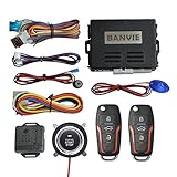
- Keyless Entry: with the basic keyless entry function. such as remote control lock/unlock door, trunk release.
- 1-Way Alarm: the siren will alarm for 8s when car body shocked, will alarm for 25s when side door opened/ footbrake pressed. Siren output is optional, could connect the original horn or extra horn.
- Remote Start: remote engine start your car in cold winter or hot summer in advance.
- Push Button Start: keyless go push button to start stop the engine, very convenient to replace the old key lock
- Push Button Auto-lock: 30s after engine stop, the system will auto-lock the push button, do not worry someone will drive your car away.
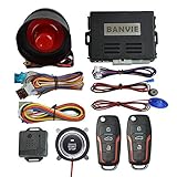
- Keyless Entry: with the basic keyless entry function. such as remote control lock/unlock door, trunk release.
- 1-Way Alarm: the siren will alarm for 8s when car body shocked, will alarm for 25s when side door opened/ footbrake pressed.
- Remote Start: remote engine start/stop your car in cold winter or hot summer in advance.
- Push Button Start: keyless go push button to start/stop the engine, very convenient to replace the old key lock
- Push Button Auto-lock: 30s after engine stop, the system will auto-lock the push button, do not worry someone will drive your car away.
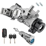
- 【REPLACEMENT】 Trouble starting your car? Replace your worn ignition lock cylinder with our VWJetta complete kit for smooth, reliable performance.
- 【PREMIUM QUALITY】 Constructed from corrosion-resistant zinc alloy and heat-treated steel, the Volkswagen Jetta lock cylinder precision-machined for smooth key rotation, consistent ignition contact, and long-lasting durability.
- 【COMPATIBILITY】 2011-2018 Volkswagen Jetta. Use the included remote key with ID46 chip, 433MHZ Freq (requires locksmith programming), or transfer your original chip for easy plug-and-play installation.
- 【REPLACE OE#】 1K0905851B, 5C6837167. This Volkswagen ignition switch housing comes without the anti-theft immobilizer module. Please transfer the original immobilizer (connected to the electrical plug) from your old switch to ensure proper function.
- 【12-MONTH WARRANTY】 If you experience any issues with the 1K0905865 assembly, we offer a hassle-free replacement or refund for 12 months, ensuring your satisfaction and confidence in your purchase.
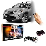
- WHAT'S INCLUDED - Complete remote start system compatible with Toyota Highlander 2014-2019. WHAT'S INCLUDED - Complete remote start system compatible with Select Toyota Vehicles (see vehicle compatibility list below).Includes an all-in-one remote starter data interface module and T-Harness. Firmware preloaded for your vehicle. All components required for installation are included. Automatic Transmission ONLY To prevent theft, the remote starter will shut down the vehicle when a door is opened.
- REMOTE START FEATURES - This is an Add-on remote start system for vehicles with existing keyless entry. Does not include remotes - this uses your factory remotes to start your vehicle by pressing the "lock" button three times. No need to carry extra key fobs! Warm or cool your car from the comfort of your home. PLUG & PLAY INSTALLATION TYPE - This kit uses a 100% plug-in T-Harness which dramatically reduces the number of wiring connections that typical systems require.
- VEHICLE COMPATIBILITY - Fits the following Vehicles; these Toyota vehicles; Toyota Highlander 2014-2019, Toyota C-HR 2018-2019, Toyota Land Cruiser 2016-2018
- OPTIONAL - Smartphone app interface module available separately (shipping limited to the continental U.S.). -- EVO-REMOTE-1 Ready: Add (2) Ultra-Compact 1-Button 1-Way Keyless Entry Remotes. -- EVO-REMOTE-4 Ready: Add (2) Long-Range 4-Button 2-Way Keyless Entry Remotes.
- MPC TECHNICAL SUPPORT - United States, Tucson, AZ. Several different methods of support available. QR code instructions included to ensure the most up to date information.

- Please use the PartFinder tool to confirm the correct model
- Fit For 5N0959839 5N0959839A 5N0959839B 5N0959839C
- Easy to install with robust design and high-grade materials
- RuiWen products undergo strict quality tests to ensure OE technical criterion
- Make sure the OE number, model, year, appearance, and function are consistent with the original one before buying
This product presentation was made with AAWP plugin.